Sep 23, 2026News & Insights
How to Read a Steel Structure BOM: A Practical Guide to Steel Building Components and Sizes
Learn how to read a steel structure BOM and understand columns, rafters, purlins, bracing, plates, bolts, steel sections, and dimensions before ordering a steel building.
Steel Building Components Explained: How to Read Columns, Rafters, Purlins and Bracing in a Steel Structure BOM
When you receive a steel structure quotation, you may see a long list of numbers such as:
- H500×250×8×12
- H600×250×10×16
- C160×60×20×2.5
- Z200×70×20×2.5
- L50×50×5
- PL12
- M20 bolts
- Ø20 tie rods
For an experienced structural engineer, these numbers immediately describe different parts of the building.
For a project owner, contractor or buyer, however, a steel BOM can sometimes look like a list of codes rather than a building.
This creates a practical problem.
You may know the total steel weight and the final price, but you may not know what the individual members actually do, why they have different dimensions, or whether the quotation includes all the necessary structural components.
Understanding the basic steel building components can make a significant difference when reviewing drawings, comparing quotations and communicating with a steel structure manufacturer.
This guide explains the major components of a typical single-story steel building, what each member does, how its dimensions are normally described, and what buyers should look for when reviewing a steel structure BOM.
Important: The dimensions shown in this article are typical examples for explaining steel member terminology and preliminary concepts. They are not construction specifications. Actual member sizes must be determined by structural calculations based on project geometry, loads, materials, connections and the applicable local design code.
1.Start With the Structural Skeleton
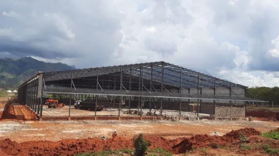
A typical steel warehouse or workshop can be understood as several layers of structure.
The main steel frame carries the major structural loads.
The secondary steel supports the building envelope and helps stabilize the main frame.
The connections transfer forces between members.
The foundation receives the reactions from the steel structure.
This means that a steel building is not simply a collection of H-beams.
Every component has a specific role in the load path.
2. Steel Columns — The Vertical Members of the Main Frame
The column is one of the most recognizable components of a steel building.
In a typical portal-frame warehouse, the column transfers roof and frame forces toward the foundation.
Depending on the structural system, the column may be subjected to both:
- Axial compression
- Bending moment
Wind and other lateral actions can also create significant bending effects.
Common Column Sections
Columns may be manufactured as:
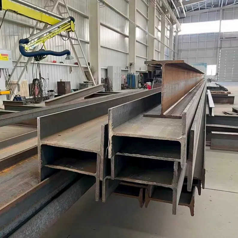
- Welded H-sections
- Hot-rolled H or wide-flange sections
- Universal Columns
- Built-up box sections
- Tapered welded sections
For fabricated steel buildings, welded built-up H-sections are particularly common because the depth and plate thickness can be adjusted according to the calculated demand.
A notation such as:
normally means approximately:
- Overall depth: 500 mm
- Flange width: 250 mm
- Web thickness: 8 mm
- Flange thickness: 12 mm
The exact notation can vary between manufacturers, so the supplier's section table should always be checked.
Another example might be:
This represents a deeper and heavier built-up section.
The larger section does not automatically mean that it is "better."
It means that the member has different geometric and material properties that may be appropriate for a different loading condition.
3. How Column Height Changes the Structural Requirement
Consider two buildings:
Building A
Building B
The floor area has not changed.
The building width has not changed.
But the structural behavior can change considerably.
The taller column has a greater unbraced length and may experience different stability and buckling requirements.
This is why a supplier should not simply use the same column section for every building.
The column design needs to consider:
- Height
- Frame spacing
- Wind load
- Roof load
- Axial force
- Bending moment
- Bracing
- Connection condition
- Steel grade
- Applicable design code
4. Rafters — The Sloping Members Above the Columns
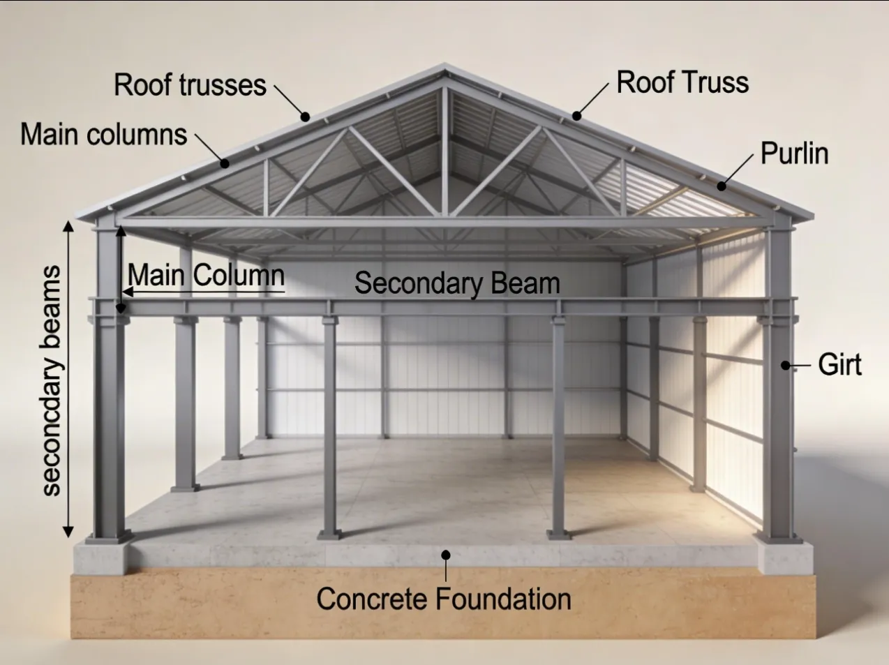
In a typical gable steel warehouse, the rafter is the sloping main-frame member between the eave and the ridge.
The rafter carries loads from the roof system toward the columns.
A simplified load path is:
For portal frames, the rafter and column work together as a rigid frame.
This is why the rafter should not be considered simply as an ordinary roof beam.
5. Typical Rafter Dimensions
For preliminary understanding, portal-frame guidance commonly uses rafter depths roughly related to the span. Published structural guidance gives a typical rafter depth around span/50 to span/60 for preliminary portal-frame sizing, with the exact value determined by engineering calculations.
For example:
20 m span
A preliminary rafter depth might be in the neighborhood of:
So a rolled section around 350–450 mm deep might be considered during preliminary design.
24 m span
A preliminary design might therefore start around the 400–500 mm depth range.
For example, depending on the applicable standard, a project might begin investigation around sections such as:
These are examples for understanding section depth, not recommended final member sizes.
The final selection depends on loads, span, frame spacing, steel grade, stability and deflection.
6. Why Portal-Frame Rafters Often Have Haunches
Look at the connection between the column and rafter.
This is called the eaves connection or knee.
It is one of the highly stressed areas of a portal frame.
Instead of making the entire rafter extremely deep, engineers often increase the section depth locally by adding a haunch.
A typical concept is:
The haunch increases the depth and bending resistance around the eaves.
Portal-frame guidance commonly indicates a haunch length of roughly 10% of the frame span as a preliminary proportion.
Therefore, for a:
a preliminary haunch length might be around:
For:
the preliminary length might be around:
Again, this is a conceptual sizing relationship, not a construction rule.
7. Purlins — The Steel Members Under the Roof
Purlins are secondary steel members that support the roof cladding.
Unlike the main columns and rafters, purlins are normally much lighter.
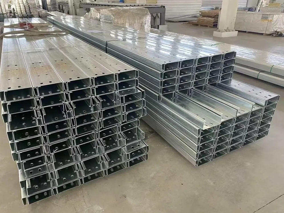
Typical cold-formed sections include:
- C purlins
- Z purlins
For example:
can describe a cold-formed C-section with approximately:
- Depth: 160 mm
- Flange: 60 mm
- Lip: 20 mm
- Thickness: 2.5 mm
Another example:
may describe a Z-section with approximately:
- Depth: 200 mm
- Flange: 70 mm
- Lip: 20 mm
- Thickness: 2.5 mm
The exact dimensions and notation depend on the manufacturer's profile system.
8. Why Purlin Thickness Matters
A buyer may see:
and:
and assume that the difference is small.
But increasing thickness changes:
- Cross-sectional area
- Weight per meter
- Strength
- Stiffness
- Connection requirements
- Cost
The correct choice depends on:
- Purlin span
- Purlin spacing
- Roof load
- Wind uplift
- Snow load
- Roof panel weight
- Deflection requirements
- Connection system
Typical purlin spacing in portal-frame buildings may fall around 1.5–2.0 m, but this varies by project and loading.
9. C Purlin vs Z Purlin
Both C and Z sections are widely used.
A simplified comparison is:
Feature | C Purlin | Z Purlin |
|---|---|---|
Section shape | C-shaped | Z-shaped |
Typical use | Roof/wall support | Roof/wall support |
Continuity | Often simple span | Often suitable for overlapping systems |
Installation | Straightforward | Requires attention to overlap direction |
Common material | Cold-formed steel | Cold-formed steel |
Typical thickness | 1.5–3.0 mm | 1.5–3.0 mm |
There is no universal rule that one profile is always better.
The choice depends on the structural system and installation method.
For longer buildings, Z purlins can be arranged with overlaps over frame lines, creating a continuous structural arrangement.
This is one reason why simply comparing:
does not tell you which quotation is better.
The complete system must be considered.
10. Girts — The Equivalent of Purlins on the Wall
If purlins support the roof, girts or side rails support the wall cladding.
Typical sections may include:
depending on the design.
Their functions include:
- Supporting wall panels
- Transferring wind loads
- Connecting wall cladding to the main frame
- Helping restrain the columns
The spacing may depend on the wall panel system and design loads.
For example, a wall system might use girts at approximately:
vertical spacing.
But this is not a universal specification.
A heavier wall panel may permit different support spacing from a lighter sheet.
11. Bracing — The Components You Don't See in the Finished Building
One of the easiest things to overlook in a steel building quotation is bracing.
Bracing can include:
- Roof X-bracing
- Wall X-bracing
- Rod bracing
- Angle bracing
- Portal bracing
- Flange bracing
- Eave struts
Typical rod bracing might use:
depending on design requirements.
Angle bracing might use:
for example.
These dimensions are examples only.
The important point is that bracing is not decorative.
It forms part of the building's stability system.
12. Roof Bracing and Wall Bracing
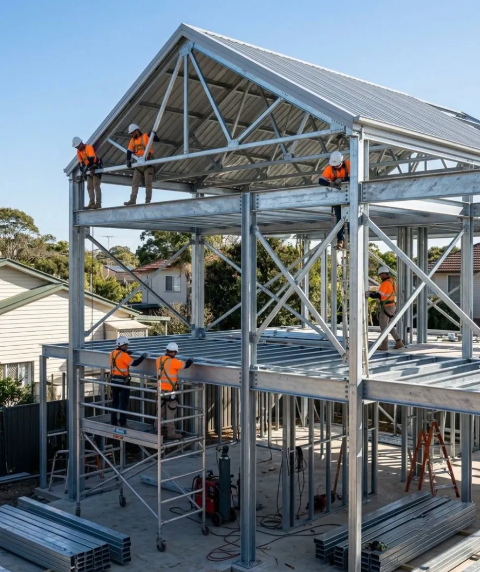
A typical steel warehouse may use X-bracing in selected bays.
Conceptually:
The bracing transfers longitudinal forces through the building.
Without a properly designed stability system, the individual portal frames cannot simply be assumed to provide all the required longitudinal stability.
Steel Construction Info specifically notes that roof and wall bracing are essential components of the overall stability system of steel framing.
13. Eave Strut — A Small Member With an Important Job
An eave strut is positioned near the roof-wall intersection.
It can serve several functions:
- Support the edge of roof cladding
- Connect roof and wall systems
- Provide restraint
- Help coordinate purlins and girts
A project may use a cold-formed C or Z section for this member.
For example:
could be used in a particular design.
But the exact profile should be determined by calculation and connection requirements.
14. Connection Plates — The Steel Behind the Bolts
When looking at a BOM, you may find items such as:
These normally refer to steel plates with different thicknesses.
For example:
generally means a 12 mm thick plate.
Connection plates can be used for:
- Beam splices
- Column splices
- Bracing connections
- Base plates
- Gusset plates
- Cleats
- End plates
- Stiffeners
A 12 mm plate and a 20 mm plate are not interchangeable simply because both are "steel plates."
The plate thickness depends on the force transferred through the connection.
15. Base Plates — Where the Steel Meets the Concrete
At the bottom of a steel column is the base plate.
A simplified arrangement is:
A typical base plate might be:
depending on the column size and foundation reaction.
Again, these are examples rather than standard sizes.
A larger column does not automatically require a proportionally larger square base plate.
The base plate needs to transfer the actual structural reactions into the foundation.
16. Anchor Bolts — Small Components, Critical Connection
Anchor bolts connect the steel column base plate to the concrete foundation.
Common diameters may include:
or equivalent anchor systems depending on the design standard.
A typical column base might use:
while a heavier frame may require:
or a different arrangement.
The number and diameter of anchor bolts should never be selected only from the column size.
The engineer needs to consider:
- Vertical reaction
- Shear
- Uplift
- Moment
- Base-plate dimensions
- Concrete strength
- Embedment
- Edge distance
- Foundation design
This becomes especially important in areas with significant wind uplift.
17. Stiffener Plates — Why Are There Extra Plates Inside an H-Section?
If you look at fabrication drawings, you may see small plates welded inside the main column or rafter.
These are often stiffener plates.
For example:
Their purpose can include:
- Preventing local web buckling
- Supporting concentrated forces
- Strengthening connections
- Transferring forces between flanges and web
Typical thicknesses might be:
depending on the calculation.
This is another reason why the total steel weight should not be evaluated only from the main H-section.
A large number of connection plates and stiffeners can contribute significantly to fabrication weight.
18. Welded H-Sections vs Hot-Rolled H-Beams
Not every H-shaped member is manufactured in the same way.
Welded Built-Up H-Section
Made by welding separate:
- Web plate
- Top flange
- Bottom flange
Example:
Advantages include:
- Flexible dimensions
- Variable web thickness
- Variable flange thickness
- Efficient customization for project requirements
- Suitable for tapered members
Hot-Rolled Section
Manufactured as a standardized rolled section.
Examples include:
depending on the regional standard.
The selection depends on the design code, availability, fabrication method and project requirements.
Neither manufacturing method is automatically suitable for every project.
19. Tapered Columns and Rafters
Many pre-engineered steel buildings use tapered welded members.
Instead of:
the member may be deeper where the structural demand is greater.
For example:
along different portions of a frame.
This allows steel to be concentrated where it is structurally useful.
Portal-frame guidance describes haunching and variable member depth as ways to increase resistance around high-moment regions while avoiding a heavier uniform section throughout the member.
For buyers, this creates an important distinction:
A 120-ton building and a 140-ton building cannot be compared fairly simply by tonnage.
The geometry and structural efficiency of the members also matter.
20. A Practical Example: What Could a 24 m Steel Warehouse Frame Look Like?
Let's take a hypothetical example.
Building
This creates approximately:
A conceptual portal-frame arrangement might therefore have frames at approximately:
The main frame could conceptually contain:
For preliminary understanding only, one might investigate rafter depths around the 400–500 mm range for a 24 m span based on common portal-frame proportional guidance.
The actual final section could be very different after considering wind, snow, seismic loads, frame spacing, cladding, openings and local code requirements.
21. Example of a Simplified Steel BOM
A simplified conceptual BOM might look like this:
Component | Example Specification | Function |
|---|---|---|
Main Column | H600×250×10×16 | Main vertical frame |
Rafter | H450×220×8×12 | Main roof frame |
Haunch | Welded built-up section | Strengthens eave region |
Purlin | Z200×70×20×2.5 | Supports roof |
Girt | C180×60×20×2.5 | Supports wall |
Eave Strut | C180×60×20×2.0 | Roof-wall connection |
Roof Bracing | Ø20 Rod | Longitudinal stability |
Wall Bracing | L63×63×6 | Wall stability |
Base Plate | 400×400×25 | Transfers column reaction |
Gusset Plate | PL10–PL16 | Bracing connection |
Stiffener | PL10–PL16 | Local reinforcement |
Anchor Bolt | M24–M30 | Connects column to foundation |
This table is for learning how to read a BOM, not for construction.
The actual project BOM should be generated from the approved structural design.
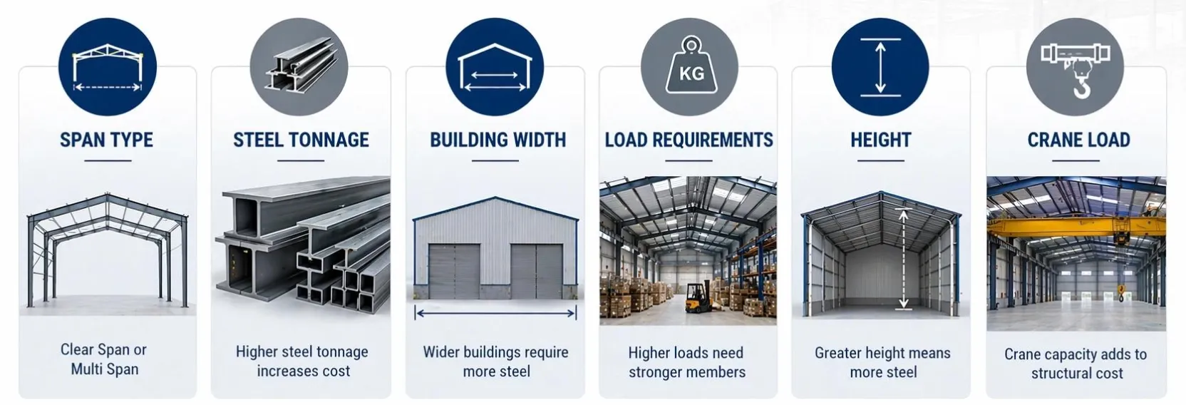
22. Why Two Buildings With the Same Dimensions Can Have Different BOMs
Now the reason becomes easier to understand.
Consider:
and:
The dimensions are identical.
But suppose Building A is:
- Inland
- Low wind
- No snow
- Simple storage
- Small doors
- No crane
While Building B is:
- Coastal
- High wind
- Heavy snow
- Industrial use
- Large doors
- Overhead crane
- Heavy equipment
The BOM may be significantly different.
The main columns may change.
The rafters may change.
The purlins may change.
Bracing may change.
Connections may change.
Base plates and anchor bolts may change.
Even the foundation reactions may change.
So the building dimensions are only the beginning of the engineering process.
23. What Buyers Should Look for in a Steel Structure Drawing
When you receive a structural drawing, don't only look for the overall dimensions.
Look for:
Main Frame
- Column section
- Rafter section
- Frame spacing
- Roof slope
- Haunch
Secondary Steel
- Purlin size
- Girt size
- Eave strut
- Bracing
Connections
- End plates
- Gusset plates
- Stiffeners
- Bolt sizes
- Weld information
Foundation Interface
- Base plate
- Anchor bolts
- Bolt layout
- Column reactions if provided
Building Envelope
- Roof panels
- Wall panels
- Insulation
- Flashings
- Openings
This gives you a much clearer understanding of what you are actually purchasing.
24. Don't Treat the BOM as Just a Weight List
A good BOM should connect the engineering model with fabrication.
For example:
is not enough by itself.
The BOM should also identify:
- Quantity
- Length
- Material grade
- Coating
- Location
- Connection accessories where applicable
Similarly:
should eventually be associated with:
- Member mark
- Length
- Quantity
- Steel grade
- Plate specification
- Welded components
- Connection details
This is what turns a structural design into a manufacturing package.
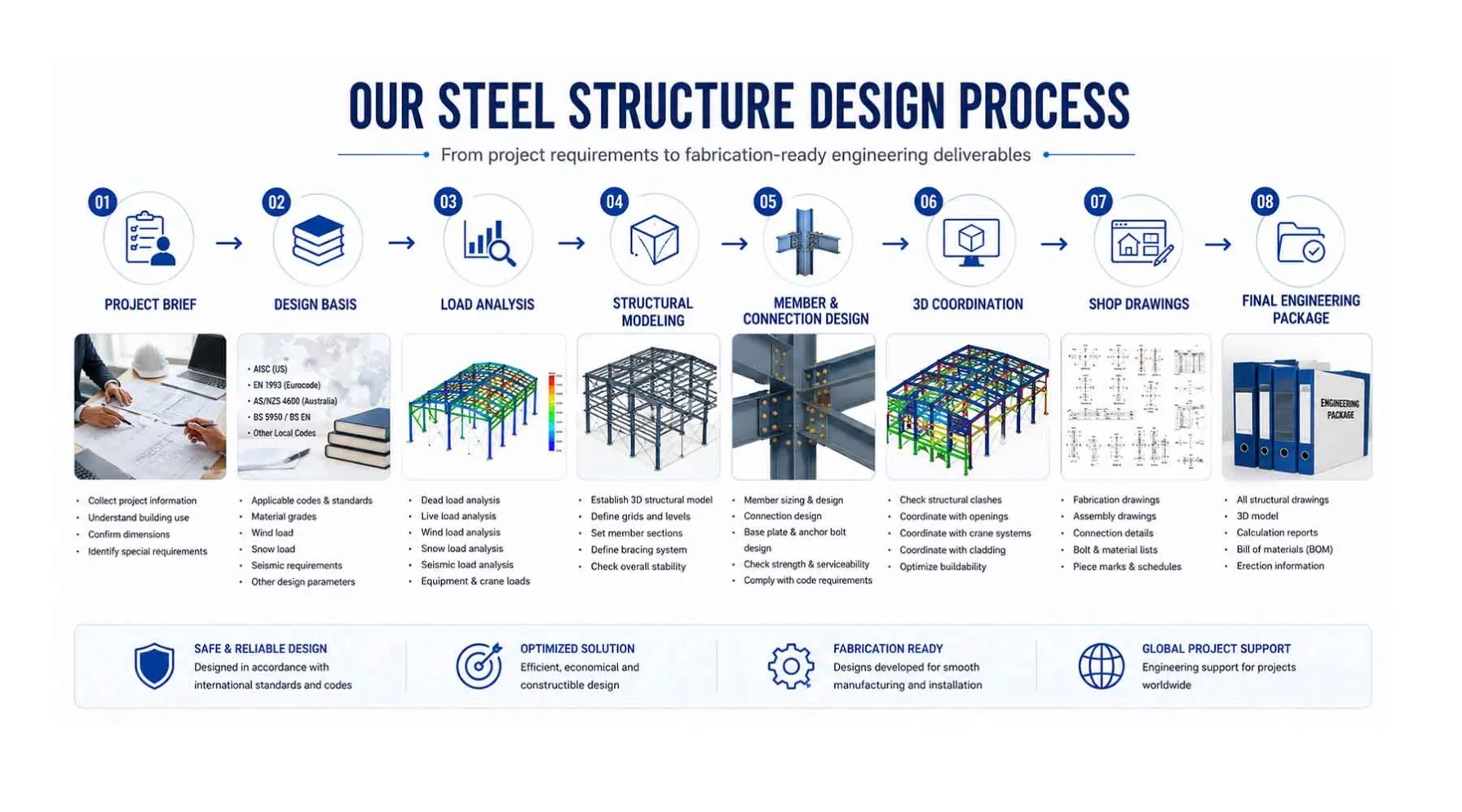
25. From Engineering to Fabrication
A properly engineered steel building eventually needs to become a set of manufacturable components.
The normal workflow is:
This is where the difference between a simple steel product supplier and a project-oriented steel structure manufacturer becomes important.
The final building is not simply a collection of steel sections.
It is the result of engineering, detailing, fabrication and quality control working together.
26. A Simple Checklist Before You Approve Your Steel BOM
Before approving a quotation or fabrication drawing, ask:
Main Frame
- What are the column sections?
- What are the rafter sections?
- Is the frame tapered?
- Where are the haunches?
- What is the frame spacing?
Secondary Members
- What are the purlin dimensions?
- What are the girt dimensions?
- What is the spacing?
- What type of bracing is used?
Connections
- What are the connection plate thicknesses?
- What bolt grades and sizes are specified?
- Are stiffeners included?
- Are base plates included?
Material
- What steel grade is specified?
- Which material standard applies?
- Are mill certificates required?
Protection
- What surface preparation is required?
- What coating system is specified?
- Is galvanizing required for any components?
Scope
- Are bolts included?
- Are purlins included?
- Are girts included?
- Are bracing members included?
- Are roof and wall panels included?
- Are gutters and flashings included?
This checklist can prevent many misunderstandings before fabrication begins.
27. When You Should Ask a Steel Engineer to Review the BOM
You should consider a technical review when:
- Two suppliers provide very different member sizes
- Steel weights are significantly different
- The project has a large clear span
- The building is unusually tall
- The project has heavy snow
- The building is in a high-wind area
- There is an overhead crane
- Large doors are required
- The project is near the coast
- You are working under a specific local building code
- You are not sure what is included in the quotation
You don't need to become a structural engineer yourself.
You simply need enough knowledge to ask the right questions.
28. Steel Structure Is a System, Not a Shopping List
A steel building may contain hundreds or thousands of individual components.
But they can be understood through a simple structural hierarchy:
Once you understand this structure, a steel BOM becomes much easier to read.
Need Help Understanding Your Steel Structure BOM?
If you already have a structural drawing, BOM or quotation and are not sure what the individual steel members mean, you can send it to us.
Our team can help you review:
- Main columns
- Rafters
- Haunches
- Purlins
- Girts
- Bracing
- Connection plates
- Base plates
- Anchor bolts
- Steel grades
- Member quantities
- Approximate steel weight
- Roof and wall systems
If you are still at the planning stage, you can start with just:
Building size + location + building use + drawings if available.
From there, the structural system can be developed around the actual project requirements.
Looking for a Complete Steel Building Solution?
Steelapro provides project-oriented steel structure solutions covering:
Design → Engineering → Shop Drawings → Material Procurement → Fabrication → Quality Control → Packing → Shipping
Whether you are planning a warehouse, workshop, factory, agricultural building or other industrial steel building, the first step is to understand the project requirements before selecting individual steel members.
Don't just look at the steel tonnage. Learn what every member in your building is doing.